Wednesday, March 12, 2008

Spline Editing in Sketcher

Spline Editing in Sketcher

clip_image001

Use this to ...

  • Edit existing splines in Sketcher.
  • Apply tangencies and curvatures to sketch splines.

Prerequisites

  • You should be in the Sketcher workbench.
  • You must have an existing sketched spline.

Process: Adding or Removing Points on Splines

1. Double-click the spline. The Spline Definition dialog displays.

clip_image001[1]


2. In the Points list of the spline definition area, select the point to edit.

clip_image002

3. Activate the required point options, Add point After, Add Point Before, or Replace Point.

4. In the Graphics window, pick the new point. Depending on the activated option, CATIA adds the point before or after the existing point, or replaces the existing point with the new point.

5. Click OK to edit the spline.

Spline Creation in Sketcher

Spline Creation in Sketcher

clip_image001


Path: Insert | Profile | Spline | Spline

clip_image002

clip_image003  Located in a fly-out on the Profile toolbar.

clip_image004

Use this to ...

  • Create a 2D basic spline while in Sketcher.

Prerequisites

  • You should be in the Sketcher workbench.

Process: Creating a Spline in Sketcher

1. In Sketcher, select Insert | Profile | Spline | Spline. The Sketch Tools toolbar changes, allowing you to enter the H and V coordinates of the spline points.

2. In the Graphics window, pick the first point for the spline to pass through.
Or
On the Tools toolbar, enter the H and V coordinates for the first point and then press TAB. The toolbar changes, allowing you to enter the next point.

3. Pick the second point for the spline to pass through. CATIA begins to create the spline.
Or
On the Tools toolbar, enter the H and V coordinates for the second point and then press TAB. CATIA begins to create the spline.

4. Continue to define points for the spline to pass through.

5. Double-click the last point that the spline passes through to create the spline.

6. Apply standard Sketcher constraints to the spline points, as required.

Tips

If you accidentally create an unwanted point in the Graphics window, press CTRL + Z to return to the last point created.

Options - Spline Creation

Options

clip_image002

Add Point After

Adds a point after the selected point in the spline definition area.

clip_image002[1]

Add Point Before

Adds a point before the selected point in the spline definition area.

clip_image003

clip_image002[2]

Replace Point

Replaces the point selected in the spline definition area with the new point picked in the Graphics window.

clip_image002[3]

Geometry on Support

Projects the spline onto the support surface. For this option to work all the defining points must lie on the support surface.

clip_image004


clip_image002[4]

Close Spline

Closes the spline from the start point to the endpoint.

clip_image005

clip_image002[5]

Remove Point

Removes the point from the spline definition.

clip_image002[6]

Remove Tangent

Removes the tangency constraint from the spline definition.

clip_image002[7]

Reverse Tangent

Reverses the tangency direction.

clip_image002[8]

Remove Curve

Removes the curvature constraint from the spline definition.

clip_image002[9]

Show Parameters

Expands the dialog and allows you to enter the tangency and curvature constraints in the Points Specifications area of the dialog.

clip_image006 clip_image007


clip_image002[10]

Points Specifications

Defines the tangency and curvature conditions for each point of the spline.

clip_image008

Constraint Type
Lets you impose tangency and curvature constraints using existing lines, curves, and planes to define the direction. Use the Explicit option to define the tangency from a plane or line and the From curve option to define the tangency from a curve.

clip_image009


Tangent Direction
Right-clicking in the Tangent Dir. box displays the pop-up menu, which allows you to quickly pick the main axes of the part or define a plane or line on the fly.

clip_image010

Tangent Tension
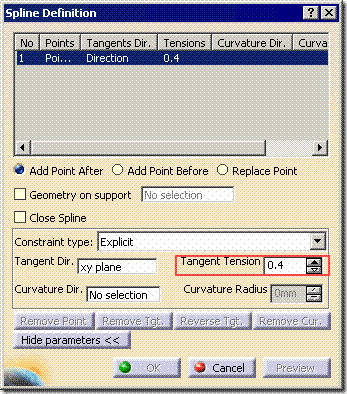
Defines the tension value or weight that the tangent direction has. A higher tension value results in the spline being pulled more in the tangency direction.

Curvature Direction
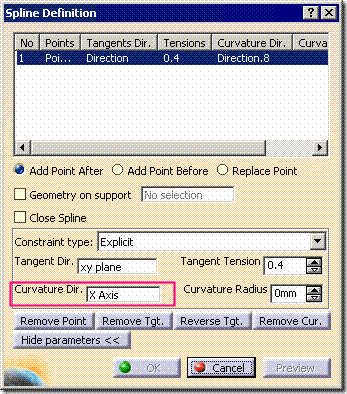
Defines the curvature direction for the selected point. The curvature direction is projected on the plane normal to the tangent.

Curvature Radius
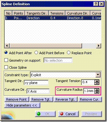
Defines the radius value for the curvature.

Frequently Asked Questions

  1. Is the spline curve generated a Bzier curve?
    A:  Only if the curve created has only 2 points because CATIA will always have to allow for 6th order in Bzier curves (2 points, 2 tangencies, and 2 curvatures). If you pick more than 2 points the result will be a multi-segmented arc with curvature continuity across the segments.

Tips

  • Right-clicking in the Points List box in the dialog displays the pop-up menu, allowing you to create geometry on-the-fly.
  • clip_image011

Deleting Points on Existing Splines

Deleting Points on Existing Splines

1. In the Graphics window, double-click on the spline. The Spline Definition dialog displays.

clip_image001 clip_image002

2. In the Points list of the spline definition area, select the point to modify.

clip_image003


3. Click Remove Point to delete the point from the spline definition.

clip_image005 clip_image006


4. Click OK to create the new spline.

clip_image007

Adding or Removing Points on Existing Splines

Adding or Removing Points on Existing Splines

1. In the Graphics window, double-click the spline. The Spline Definition dialog displays.

clip_image001

2. In the Points list of the spline definition area, select the point for modification.

clip_image002


3. Activate the required point option, Add point After, Add Point Before or Replace Point.

clip_image003


4. In the Graphics window, pick the new point. Depending on the activated option, CATIA adds the point before or after the existing point or replaces the existing point with the new point.

clip_image004 clip_image005

5. Click OK to create the new spline.

clip_image006

Spline Creation and Editing
Spline Creation and Editing

clip_image001

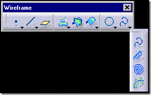
Path: Insert | Wireframe | Spline

clip_image002  Located in a fly-out on the Wireframe toolbar.
clip_image003

Use this to ...

  • Create a spline in 3D space.

Key Points

  • Unlike the Sketcher spline command, you need existing construction geometry before you can access the Spline dialog,

clip_image004

Prerequisites

  • You should be in the Generative Shape Design workbench

Process: Creating Splines Through Existing Points

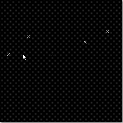
1. Select Insert | Wireframe | Spline. The Spline Definition dialog displays.
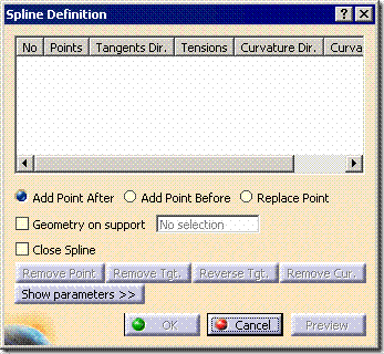
clip_image005

2. In the Graphics window, pick the first point that the spline passes through.


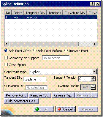
3. As necessary, click Show Parameters to expand the dialog.

clip_image006


4. As necessary choose an element you may want to define as a direction of tangency coming off of the point. If you choose a plane then the type will automatically switch to Explicit in the Constraint type list.

clip_image007

clip_image008

Or
If you choose a line then the type will automatically switch to From Curve in the Constraint type list.

5. As necessary in the Tangent Tension text box, enter the tension value coming off of the point in the tangency direction. If you had chosen a plane then the tension would default to 0, if you had chosen a line then the tension value would default to 1.

6. The Curvature Dir. box will become active.
clip_image009


7. As necessary in the Curvature Direction box. Then in the Graphics window, pick any curve as the curvature reference.
clip_image010


8. In the Curvature Radius text box, enter the required radial curvature value for the value of curvature at that point on the spline curve.
clip_image011

9. In the Graphics window, pick the next point that the spline passes through.

10. Continue to define the tangency and curvature for the second point, if required.

11. Continue to define points and their associated tangencies and curvature.

12. Click OK to create the spline.